FINAL 3D MODEL
I was pleased with the final outcome, although I do think a few improvements should be made such as the materials used, and the pattern on the model. I think the etching would of worked better instead of the acrylic pieces. I am going to make a smaller version of this model with some changes then both models will be ready to present to my client.

3D MODELS FOR SCULPTURE ( PROCESS OF MAKING )
This was the final design done on the Rhino cad software (outlines in the top view port). It is saved as DXF file, then uploaded onto a computer software that works with the laser machine. The line, width and cutting speed are set according to the material being used then the design is ready to be cut. As you can see in the image below the lines appear in three colours. This is done to enable the laser to read whether lines are cut or etched.

The laser cutting process took around 30 - 40 minutes to complete. This video shows part of the cutting process on the laser machine. I used a grey acrylic material for the model as it can be cut, etched and shaped using a strip heater.
After the model was cut on the laser machine a strip heater is used to bend the acrylic (thermoplastic). Line bending is the actual term used for this process, It involves heating the acrylic sheet over the strip heater until it becomes soft and pliable then bending it. It was easy to assess where the bends should be, simply looking at the image of the design.
Although it is more accurate to draw faint lines on the material first.


 |
| Ilsa Parry - Product Designer - Best known for winner of Phillipe Starks Design for Life BB2. |


This was the outcome after the line bending process. Although the model is standing upright it is not secure enough. This is something I would need to develop further. An alternative to the triangular base could be a square base giving the model extra support.
 When laser cutting the model I did not remove the plastic film on the acrylic assuming it would cut and etch through it. What happened instead was the heat from the laser melted the plastic film into the etched parts, making it difficult to remove.The pieces in the left image will be stuck down on the areas I originally wanted etched. I chose the yellow acrylic to match the company's logo.
 DISPLAYS AT MANCHESTER ART GALLERY
The first two photographs / images of the Slice chair where by far the most intriguing chair designs on display. I have included these as further research. I am interested in the design process, mainly because it was a similar concept to one of my initial ideas ( car design ).
Mathias Bengtsson's - slice chair
combines organic shapes with cutting edge technology. Slice is constructed as an assemblage of horizontal cross-sections that stack together into a uniquely lateral profile. First it is drawn by hand and later modeled by clay, laser cut to a thickness of only 3mm, each individual layer resembles a two dimensional abstraction more then it does as a high tech component.


This chandelier shade was designed by Jurden Bey in collaboration with Droog design. Droog is a conceptual design company founded in 1993 by Rennie Ramakers and Gijs Bakker at the milan furniture fair. Like many of the re-use projects by droog design, the light shade updates an old design, it uses a semi transparent mirror around an old chandelier. When the light is off only the cylinder is seen (see image on left). When the light is switched on it reveals the chandelier and projects its inner beauty.
3D Model


DESIGN RENDERED USING RHINO CAD
This image has been manipulated and rendered using the Rhino design software. It shows the clients company (Cats protection) with the cat design / sculpture outside the building. Alternatively Photoshop could be used to create similar images once the 3D image (sculpture) is finalized and saved. Although Rhino cad and Photoshop have many similarities, the main difference is that Photoshop is a 2D design software, and Rhino is a 3D design software.

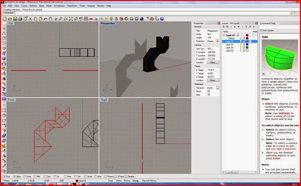
FINAL SCULPTURE AND MERCHANDISE DESIGNS ON RHINO CAD
This image was my first attempt to visualizing my geometric cat model on Rhino cad this shows all for views of the model. The process was straightforward and all I basically had to do was draw the outline of the cat to set measurements. Then using the surface tool outline each shape, this allowed me to extrude the surfaces to form a 3D model.

This is similar to the first image except the design is set to ghosted mode (perspective view port).If I turned the model around in the perspective view port there is no surface at the back. This resembled shelves or a cabinet which is not the outcome I wanted, I thought about putting a surface on both sides but decided this was not interesting enough.

At this point I decided to change the design to something a bit more basic and easier to construct but would have more of an effective outcome. It was a 2D model but the lines where the shapes on the cat intersect will be slightly bent. This can be done easily on acrylic using a hot air blower or a strap heater.


2D Technical Drawings


USING RHINO CAD TO CREATE 3D MODELS
Rhinoceros (rhino cad) is a 3D modelling software used in design industries. These include CAD/ CAM, industrial design, architecture, product design, Jewelry design, rapid prototyping, as well as multimedia and graphic design industries. I have been following an introduction course using this program which shows the development of 3D models. I will need to expand my skills as I will be using this program to create 3D models of my sculpture and merchandise designs. Here are a range of screenshots showing different stages creating a torch, a castle and a duck.
CREATING A TORCH
 In this first image a cylinder and a Tcone are created for the flashlight body. This is done by using the cylinder command or right clicking on the box tools and selecting the cylinder tool ( a radius and length will need to be set). The cylinder can be changed to shaded mode by right clicking on the perspective title and selecting shaded. The Tcone is created in the same way and joined to the centre base of the cylinder using the Boolean union tool. A copy of the Tcone is then made which is used to cut out the center of the original Tcone. The Boolean difference tool is used for this.
Next the inside of the flashlight is cut out. Similar to the way the hollow Tcone is created, a cylinder is made ( see image to the left) and is used to cut the center of the flashlight using the Boolean difference tool.

Finally the lens and button are added and the torch is rendered .The lens is a thin cylinder which is placed in the center between the Tcone and the base of the flashlight body. To give the lens a realistic look its color can be set to transparent by opening the materials editor and adjusting the transparency. The button is a small sphere and placed on the body its usually easier to do this on the front view port. A gloss finish can also be set on the materials editor.
Here a castle is created using some basic geometric shapes.

A set of blocks are created by selecting the box/cube under solid tools and lining them on top of another in the top view port. This image shows the cubes in all view ports. There are four view ports top, perspective, front and right. 3D models are visualized in the perspective view port.


The castle is then set to rendered mode and the colors/ textures can be manipulated. This is done by window selecting the area on any of the view ports, then selecting render tools, then set render color. Surface textures can also be added for example "brick" by downloading a brick texture, then adding it to the texture palette under render.

A DUCK


DIGITAL SCULPTURE PROJECT DESIGN SHEETS
Initial Ideas for Sculpture....


Initial ideas and developing ideas for Sculpture....


Ideas for merchandise....

Here are a few of my design sheets for sculpture and merchandise ideas.

RISK ASSESSMENT
Risk assessments are used to identify hazards and risks. Once these have been identified, processes are put in place to eliminate the hazards and reduce the risks where possible. If they cannot be eliminated they are minimized by the use of physical controls or, as a last resort, through systems of work and personal protective equipment


NON DISCLOSURE AGREEMENT


Non disclosure agreements, sometimes called NDAs
 are formal agreements intended to protect information considered to be proprietary or confidential. One party agrees to give a second party information about its business or products, then an NDA is signed to ensure no confidential information is shared with anyone else for a specific period of time. It is vital a designer sends a NDA to prospective clients to sign before sending any design ideas or concepts. This protects the designers work being used elsewhere and you have the right to take legal action against anyone infringing the contract terms. Here is a draft version of my own NDA, which I will send along with a contract to clients interested in my designs.
Subscribe to:
Comments (Atom)