DISPLAYS AT MANCHESTER ART GALLERY

The first two photographs / images of the Slice chair where by far the most intriguing chair designs on display. I have included these as further research. I am interested in the design process, mainly because it was a similar concept to one of my initial ideas ( car design ). 

Mathias Bengtsson's -  slice chair 
combines organic shapes with cutting edge technology. Slice is constructed as an assemblage of horizontal cross-sections that stack together into a uniquely lateral profile. First it is drawn by hand and later modeled by clay, laser cut to a thickness of only 3mm, each individual layer resembles a two dimensional abstraction more then it does as a high tech component. 


Droog design - Chandelier shade (1999)
This chandelier shade was designed by Jurden Bey in collaboration with Droog design. Droog is a conceptual design company founded in 1993 by Rennie Ramakers and Gijs Bakker at the milan furniture fair. Like many of the re-use projects by droog design, the light shade updates an old design, it uses a semi transparent mirror around an old chandelier. When the light is off only the cylinder is seen (see image on left). When the light is switched on it reveals the chandelier and projects its inner beauty.  
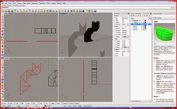

3D Model 


DESIGN RENDERED USING RHINO CAD

This image has been manipulated and rendered using the Rhino design software. It shows the clients company (Cats protection) with the cat design / sculpture outside the building. Alternatively Photoshop could be used to create similar images once the 3D image (sculpture) is finalized and saved. Although Rhino cad and Photoshop have many similarities, the main difference is that Photoshop is a 2D design software, and Rhino is a 3D design software. 


FINAL SCULPTURE AND MERCHANDISE DESIGNS ON RHINO CAD

This image was my first attempt to visualizing my geometric cat model on Rhino cad this shows all for views of the model. The process was straightforward and all I basically had to do was draw the outline of the cat to set measurements. Then using the surface tool outline each shape, this allowed me to extrude the surfaces to form a 3D model.


 This is similar to the first image except the design is set to ghosted mode (perspective view port).If I turned the model around in the perspective view port there is no surface at the back. This resembled shelves or a cabinet which is not the outcome I wanted, I thought about putting a surface on both sides but decided this was not interesting enough.  


At this point I decided to change the design to something a bit more basic and easier to construct but would have more of an effective outcome. It was a 2D model but the lines where the shapes on the cat intersect will be slightly bent. This can be done easily on acrylic using a hot air blower or a strap heater.


2D Technical Drawings


USING RHINO CAD TO CREATE 3D MODELS


Rhinoceros (rhino cad) is a 3D modelling software used in design industries. These include CAD/ CAM, industrial design, architecture, product design, Jewelry design, rapid prototyping, as well as multimedia and graphic design industries. I have been following an introduction course using  this program which shows the development of 3D models. I will need to expand my skills as I will be using this program to create 3D models of my sculpture and merchandise designs. Here are a range of screenshots showing different stages creating a torch, a castle and a duck.


CREATING A TORCH
                                                                               
In this first image a cylinder and a Tcone are created for the flashlight body. This is done by using the cylinder command or right clicking on the box tools and selecting the cylinder tool ( a radius and length will need to be set). The cylinder can be changed to shaded mode by right clicking on the perspective title and selecting shaded. The Tcone is created in the same way and joined to the centre base of the cylinder using the Boolean union tool. A copy of the Tcone is then made which is used to cut out the center of the original Tcone. The Boolean difference tool is used for this.

Next the inside of the flashlight is cut out. Similar to the way the hollow Tcone is created, a cylinder is made ( see image to the left) and is used to cut the center of the flashlight using the Boolean difference tool.         


Finally the lens and button are added and the torch is rendered .The lens is a thin cylinder which is placed in the center between the Tcone and the base of the flashlight body. To give the lens a realistic look its color can be set to transparent by opening the materials editor and adjusting the transparency. The button is a small sphere and placed on the body its usually easier to do this on the front view port. A gloss finish can also be set on the materials editor.                                                  


 A CASTLE

  Here a castle is created using some basic geometric shapes.                                            
                                             

A set of blocks are created by selecting the box/cube under solid tools and lining them on top of another in the top view port. This image shows the cubes in all view ports. There are four view ports top, perspective, front and right. 3D models are visualized in the perspective view port


The cubes are changed from wire frame mode to shaded mode,as you can see in this image on the perspective view port the cubes are no longer transparent. Grid snap is set by clicking on the statues bar below the front and right view port. Grid snap keeps all the squares in line and precisely on top of another. Once one row of cubes are completed and joined ( selecting join tool ) the other three rows can be copied using the copy tool.
 The process of creating the cube shapes and joining them is continued till the final structure of the castle is made. The spheres and cones can all be found under the solid tools. These shapes are then added, it is often easier to do this in the top view port.


The castle is then set to rendered mode and the colors/ textures can be manipulated. This is done by window selecting the area on any of the view ports, then selecting render tools, then set render color. Surface textures can also be added for example "brick" by downloading a brick texture, then adding it to the texture palette under render.


A DUCK


 For the ducks body two spheres are created and are set to deformable, to allow a change to the form. The rebuild tool is selected under the edit bar, and the point is set to 8 and degree to 3. Next the points are turned on and the body and head can be adjusted. Scale 1D command can also be used to drag the body in one direction.


 This stage shows a neck and a beak added to the duck. Curves are created to areas that need to be split and are used as a cutting tools. The curve from the head is extruded until it intersects with the body. The curves are then deleted and the blend surface tool is to create the neck by adjusting the blend bulge(dialogue box)to 1.0,1. The neck will connect to the body atomically.


Here the duck has been rendered and the eyes are added. First all the areas are joined (using the join tool) except an area you want to render e.g leave the beak out. The properties command is used to assign the materials and render colour is chosen. Select perspective and click render display this will show the colour of the beak. The same applies to the colour of the body. A gloss can also be set.


Finally the eyes are created using an the ellipsoid tool and a circle in made in the centre of it. This is extruded and used as a cutting tool. The colour in then changed to black. Orient on surface tool is used to allow the eyes to be placed on the ducks body and the mirror is then used to copy the eye on the other side of the ducks head. The frames can be deleted and the duck is then completed.